RG1
IRIG Timecode Receiver and Generator
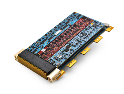
The RG1 Time Code receiver synchronizes to IRIG-A/B/G time codes and provides precise time in a memory register, for the host SBC.
The IRIG output of the card can be used to synchronize other IRIG time code readers. Additionally, the RG1 includes a real-time clock (RTC) that may be used as a reference source for IRIG master applications, to free the system processor from the task of updating the master timer.
The most common format is IRIG-B, but the module can also support IRIG-A and IRIG-G formats as well.
Features
- Analog Input, AM ASK IRIG Receiver (Formats A, B or G): Signal level to 0.5 to 10 Vpp; 3:1 modulation ratio; Zin: 20k or 50 ohm, selectable; Isolated input (high CMR limited only by isolation)
- Node Capacity (maximum): 3-Node; 2 x 3 ports and 1 x 2 ports
- Digital Input IRIG Receiver (Formats A, B or G): DCLS; Isolated input
- Analog Output, AM ASK IRIG Generator(Formats A, B or G): Configurable signal level (0 to 18 Vpp for high-Z or 0 to 9 Vpp for 50 ohm load); Modulation ration: 3:1
- Digital Output IRIG Generator (Formats A, B or G): DCLS encoding; Signal Level: RS-232 or RS-422/485
- IRIG Generator (Formats A, B or G): 10 MHz Reference output (RS-422)
- 1-PPS Output (RS-232 or RS-422) Digital Output
- Real-Time Clock (RTC): May be used as a reference source for an IRIG master
- Event Input Signal: RS-232 or RS-422/485
- Built-in Test & Functions: Over-current protection/status
- Supported IRIG Protocols: A000, A001, A002, A003, A004, A005, A006, A007, A130, A131, A132, A133, A134, A135, A136, A137, B000, B001, B002, B003, B004, B005, B006, B007, B120, B121, B122, B123, B124, B125, B126, B127, G001, G002, G005, G006, G141, G142, G145, G146
- IRIG AM input or Output: Formats A, B, G
- IRIG AM input signal level: 0.5 to 10 Vp-p
- IRIG AM input modulation ratio: 3:1
- IRIG AM input impedance: 20k or 50 ohm, selectable
- IRIG AM output signal level: 0 to 9 V p-p min. (50 Ω load) or 18 V p-p min. (hi-Z load); configurable in 256 steps
- IRIG AM output modulation ratio: 3:1
- IRIG DCLS Input or Output: Formats A, B, G
- IRIG DCLS input decoding: DCLS (DC level shift) decoding
- IRIG DCLS output encoding: DCLS (DC level shift) encoding
- IRIG DCLS input or output signal level: RS-232 or RS-422*/485
- 10 MHz reference output: RS-422*
- External 1PPS output: RS-232 or RS-422*
- External 1PPS output Pulse Width: 1 ms – 100 ms, configurable
- Event Input, GPIO: RS-232/422*/485, configurable. Captures the time on the rising or falling edges. This transition will also generate an interrupt.
- Isolation: Module power source (ISO-GND) and I/O to system ground is ≥500 VDC
- Power: 5 VDC / 850 mA (max); ±12 VDC @ 20 mA (max est.)
- Weight: 1.5 oz. (42 g)
| Reference Synchronization Accuracy | The reference accuracy and 1PPS output for AM inputs when slaved to a reference source should fall within:
The reference accuracy and 1PPS output for DCLS inputs when slaved to a reference source should fall within: The reference accuracy and 1PPS output for GPS inputs (not applicable to RG1) when slaved to a reference source should fall within: ±100 ppb (±100ns) |
| Free-Running Drift/Accuracy | The drift per second when free-running after losing lock with an AM reference source input should fall within:
The drift per second when free-running after losing lock with an DCLS reference source input should fall within: The drift per second when free-running after losing lock with a GPS reference source (not applicable for RG1) should fall within: ±280 ppb/sec (±280 ns/sec) |
(All) specifications pending design verifications and qualification. Specifications listed are defined at/to the module boundary.
*RS-422 Hardware Interface: Effectively implemented by programming the channel(s) for RS-485 differential signal level AND programming receiver input termination (120 ohms).

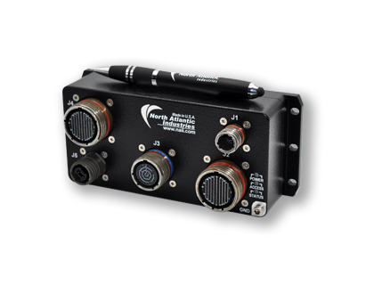
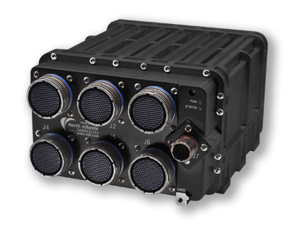
NAI’s Configurable Open Systems Architecture™ (COSA®) offers a choice of over 100 smart I/O, communication, and Ethernet switch functions, providing the highest package density and greatest flexibility of any multifunction I/O board in the industry. Preexisting, fully-tested functions can be combined quickly and easily in an unlimited number of ways. Choose the ideal platform for your application below. Each I/O function has dedicated processing, unburdening the system Single Board Computer (SBC) from unnecessary data management overhead.
Related COSA® Products


Single Board Computers

Nano Interface Units

Sensor Interface Units
North Atlantic's resource center is where you will find information on warranty and repairs, details of our Product Lifecycle Management and Configuration Management programs – and much more.
Visit Resource Center

